Spreadsheet State Machines :: State Machines
A state machine is a mechanism that exists in two or more states and transitions from one state to another state based on the current state and on the current inputs.
Combination locks and push-button light switches are mechanical state machines, a computer is an electronic state machine. and a compiler is a software based state machine,
A transition from one state to another is caused by an event. For a computer the event is clock driving the digital circuits. For a compiler the event is the arrival of a recognized token. Since this project is geared toward FPGAs our events will usually be from a clock, although some designs might use arrival of a character from, say, a DMA channel.
In 1956 Edward Moore presented a paper which gave a block diagram of a generalized state machine. The diagram below shows the components in a Moore state machine.
The reset line puts the state memory into a known state. The reset line is most often asserted at circuit power up. The clock line latches the next value into the state memory. The transition logic computes the next state based on the current state and on the inputs. The output logic transforms the state values into signals that are useful for the specific application.
AN EXAMPLE

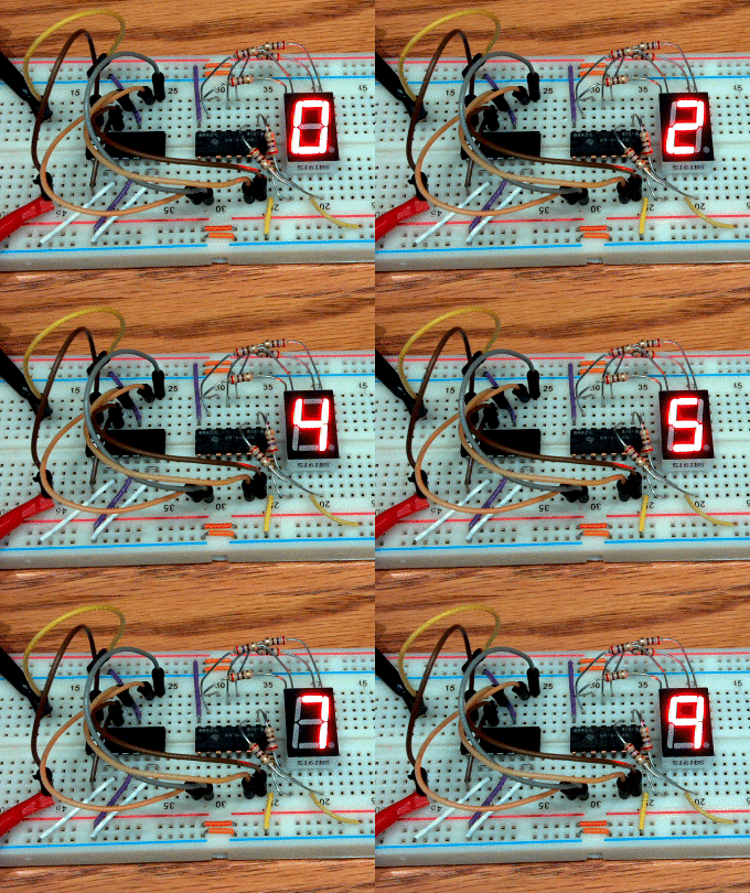
A one digit up counter is a good example of a Moore state machine. In this TTL circuit the output is the display, the output logic is in in the 74LS47 BCD-to-7segment chip, and the state and input logic are in the 74LS90 counter. Note that the digit 6 is what we now consider a hexadecimal B.
A nice explanation of the 74LS90 is available here:

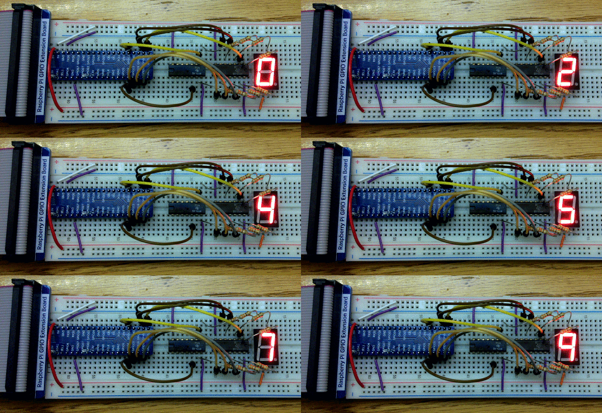
You can program a Raspberry Pi to act as a one digit counter. The circuit to the right uses two 74LS06 inverters to buffer the signals from the Raspberry Pi since the Pi output pins can not drive the LEDs in the display directly. The C program for this is available here: digitcount.c.

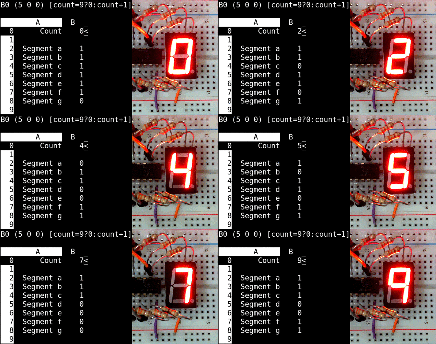
You can also use sc, the spreadsheet calculator, to control a seven segment display on an RPi. The spreadsheet uses calls to the bash shell to set the LED segments and to sleep for a short while. The sc program for single digit counter is available here:digitcounter.sc.

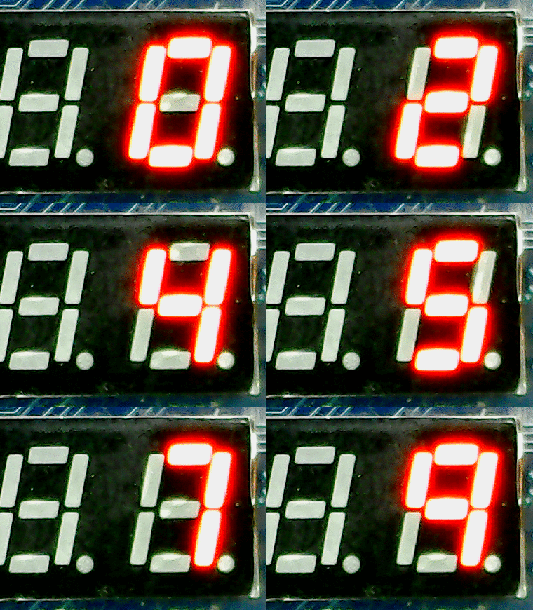
The Basys-3 FPGA board has a four digit display. The figure to the right shows the digit counter running on the FPGA board. The source code for the FPGA based digit counter is available here:digitcount.v.
Note that the input logic section of a Moore state machine does not have any state or memory. This means that you have to implement the input logic entirely as a conditional statement. The code below shows how each of the digit counter state machines used a conditional assignment.
    count = (count == 9) ? 0 : count + 1;      // from digitcount.c
    let count = (count=9)?0:count+1            // from digitcount.sc
    count <= (count == 9) ? 0 : count + 1;     // from digitcount.v
The whole idea of programming with a spreadsheet comes down to how well can we visualize state variables and their next state computation. Every cell in a spreadsheet needs a single assignment so every cell might have complex conditional assignments.
SHADOW VALUES
The diagram on the right shows a simple Moore state machine with three state values. The next value for all three depends on the current value of all three. To be correct all three values need to change at the same time. The following code will not work since the new values of B and C would be computed with the wrong value of A.
LOOP clock = 0 TO 10000 STEP 1
    A = fa(A, B, C)
    B = fb(A, B, C)
    C = fc(A, B, C)
NEXT clock
The solution to this problem is to add a "shadow" value that holds the next value of each variable until the end of the loop when the "visible" values are updated. Edge triggered flip-flops actually have two flip-flops in them for a similar reason.
LOOP clock = 0 TO 10000 STEP 1
    Ashadow = fa(A, B, C)
    Bshadow = fb(A, B, C)
    Cshadow = fc(A, B, C)
    A = Ashadow
    B = Bshadow
    C = Cshadow
NEXT clock
Spreadsheets order the computation of the cells from top to bottom or from left to right. Either way introduces the problem described above. You can carefully design your spreadsheet to overcome this but doing so would be difficult and error prone. The major change we must make to our target spreadsheet is to add a shadow value to each cell and to update the visible cell values at the end of each update cycle.